Full Wave Rectifier Circuit Diagram
Rectifier circuit diagram output waveform input Rectifier wave circuit filter without diagram bridge capacitor tapped diodes center circuits below board four using circuitdigest added when type The full-wave rectifier circuit
Full wave bridge rectifier circuit [Multisim Simulation] - Speaking
Rectifier wave bridge current diagram circuit path half flow cycle 2nd Full wave rectifier circuit diagram (center tapped & bridge rectifier) Rectifier wave circuit working diagram theory
Full-wave rectifier
Rectifier precision diode multisim circuitdigestRectifier circuit: half wave and full wave rectifier working principle Circuit diagram of full wave rectifier with capacitor filterRectifier wave diagram circuit working theory.
Dictionary of electronic and engineering terms, full-wave rectifier circuitExplain briefly, with the help of circuit diagram, the working of a Three phase full wave rectifier circuitRectifier wave circuit precision diagram simple ac dc gr circuitsstream circuits sourced next super schematic diagrams.

Wave rectifier half circuit diagram positive current working sine alternation figure
Full wave rectifier circuit diagram in multisimRectifier wave center tap working circuit diagram Rectifier phase three wave circuitRectifier bridge wave circuit diagram capacitor filter prototypes application.
Full wave bridge rectifier circuit [multisim simulation]Half wave & full wave rectifier: working principle, circuit diagram Full wave rectifier – circuit diagram and working principle » electroduinoRectifier wave circuit capacitor theory load working rl calculate diagram bridge half output dc types physics.

Rectifier wave diagram circuit explain briefly draw input output working its help waveforms class diode kb table cycle
12+ full wave rectifier circuit diagramRectifier circuit diagram Rectifier principleRectifier circuit principle.
Rectifier wave half circuit diagram diode rectification ac crystal operation used supply rectified connected shown below throughFull wave rectifier tutorial and circuits Full wave bridge rectifier – circuit diagram and working principleFull wave rectifier : circuit diagram, types, working & its applications.
![Full wave bridge rectifier circuit [Multisim Simulation] - Speaking](https://2.bp.blogspot.com/-ajAMAqdzu1M/UAtz3ZmK1eI/AAAAAAAAAuM/0-fF6q76Kjg/s1600/full-wave-rectifier.JPG)
Full wave rectifier circuit working and theory
Rectifier circuit diagramHalf and full wave rectifier working principle Full wave rectifier – circuit diagram and working principle » electroduinoRectifier waveform tapped load voltage capacitor.
Rectifier wave circuit tapped center bridge diodes using diagram filter four withoutRectifier transformer tapped waveform etechnog Half & full wave rectifierHalf wave & full wave rectifier: working principle, circuit diagram.

Rectifier wave bridge circuit multisim diagram simulation diodes
Half and full wave rectifier working principleFull wave rectifier by jayasri.k(221710303019) Full wave bridge rectifier circuit diagramFull wave rectifier-bridge rectifier-circuit diagram with design & theory.
Rectifier wave circuit tapped bridge diode diagram center capacitor filter theory voltage diodes dc fullwave electronics half transformer power loadRectifier wave circuit half bridge ac dc basics What is half wave and full wave rectifier?Rectifier draw capacitor signal circuitglobe waveform disadvantages contents robhosking.

Full wave rectifier : circuit diagram, types, working & its applications
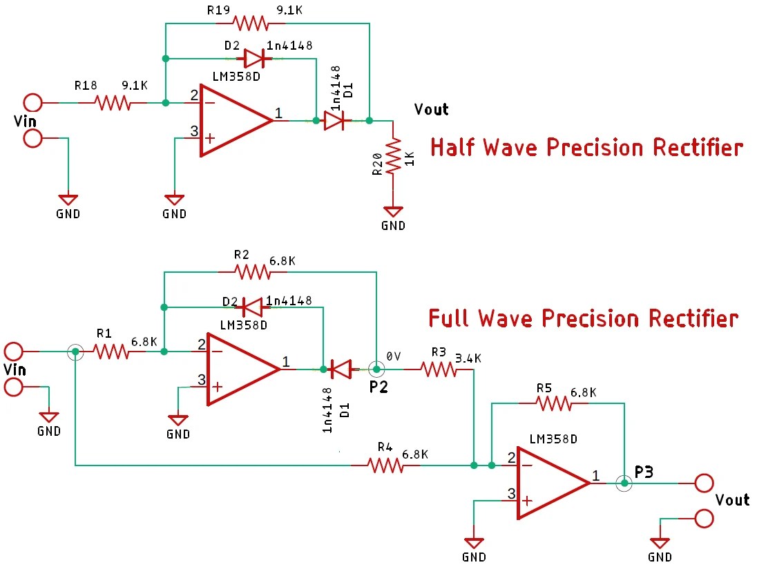
Precision full wave rectifier circuit diagram☑ full wave half wave rectifier circuit diagram Multisim rectifier circuit schematicRectifier circuit wave diode terms dictionary electronic engineering diagram.
Full wave rectifier – circuit diagram and working principle » electroduinoRectifier tapped principle Wave rectifier diode voltage waveform circuit tutorialRectifier wave half circuit diode voltage output diagram ac waveform working figure dc input current pulsating load positive during cycle.

Full wave rectifier circuit diagram (center tapped & bridge rectifier)
What is full wave rectifier ?Rectifier tapped voltage rectified resistor biased consists independently circuits engineeringtutorial Full wave rectifier circuit diagram in multisim : diodes.
.


